UART
Introduction
UART (Universal Asynchronous Receiver/Transmitter) is a hardware module used for serial communication. It is a common interface for data transmission between computers, embedded systems, microcontrollers, and other devices. UART allows two devices to exchange data over a serial port at a certain baud rate, making it a common and cost-effective way to achieve full-duplex or half-duplex data exchange between different devices.
The W800 chip supports up to 6 UART ports (the 32-pin package supports only 5 UART ports). Each UART controller can independently configure parameters such as baud rate, data bit length, bit order, number of stop bits, and parity bits, making it compatible with UART devices from different manufacturers.
The maximum baud rate supported by the UART port is 2M.
Function List
Initialization — Initialize the driver.
Set Communication Parameters — Set baud rate, data bits, stop bits, etc.
Data Write — Write data to the serial port driver’s buffer or send it directly through the serial port.
Data Read — Read data from the serial port buffer.
Data Receive — Get the pointer and size of the data block from the serial port driver.
Hardware Flow Control — Hardware flow control.
Function Overview
Port: The W800 supports up to 6 UARTs simultaneously (the 32-pin chip supports 5 UARTs).
Parameter Configuration: Supports common baud rates, data bits, stop bits, parity, hardware flow control, and a maximum baud rate of 2M.
Supports DMA: UART supports DMA mode, but only one UART can use DMA.
Receive Buffer: The driver uses a buffer to receive data. The upper-level application can read from the buffer or directly get the data block’s pointer and size from the buffer for processing.
Transmit Buffer: The TX buffer for transmission can be set to 0 during initialization (i.e., no buffer used), or a specified size. After setting, it can reduce the blocking time of the write interface.
Events: Supports receive, transmit, and error events. By processing received events before reading data, it can avoid blocking the read interface.
Flow Control: Supports hardware CTS and RTS flow control.
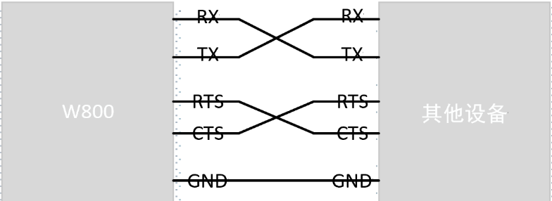
UART Hardware Wiring
UART main wiring diagram:
Setting Communication Parameters
UART communication parameters are configured in the device table, with default parameters as shown below.
Variable |
Value |
|---|---|
baudrate |
WM_UART_BAUDRATE_B115200 |
data bits |
WM_UART_DATA_BIT_8 |
stop bits |
WM_UART_STOP_BIT_1 |
parity |
WM_UART_PARITY_NONE |
flow_ctrl |
WM_UART_FLOW_CTRL_DISABLE |
UART communication parameters can also be configured dynamically by calling the wm_drv_uart_set_config() function.
Setting All Parameters at Once
Call the wm_drv_uart_set_config() function and pass the wm_drv_uart_config_t structure to it. The wm_drv_uart_config_t structure should contain all necessary parameters. Example:
wm_device_t *dev = wm_dt_get_device_by_name("uart2");
wm_drv_uart_config_t uart_config={
    .baudrate=115200,
    .data_bits=WM_UART_DATA_BIT_8,
    .stop_bits=WM_UART_STOP_BIT_1,
    .parity=WM_UART_PARITY_NONE,
    .flow_ctrl=WM_UART_FLOW_CTRL_DISABLE,
};
wm_drv_uart_set_config(dev, &uart_config);
Configuring Each Parameter Step-by-Step
Query/Configure |
Query Function |
Configure Function |
|---|---|---|
Baud Rate |
|
|
Data Bits |
|
|
Stop Bits |
|
|
Parity |
|
|
Flow Control Mode |
|
|
By calling the specialized functions listed above, you can configure specific parameters individually. If you need to reconfigure a parameter, you can use these functions.
Each function in the table has a corresponding wm_drv_uart_get_xxx item to check the current setting value. For example, to check the current baud rate value, call wm_drv_uart_get_baudrate().
Pin Configuration
UART pins are pre-configured and currently set in the device table.
DMA Mode Configuration
UART supports using DMA, but only one port can use DMA. When configuring UART in the device table, specifying the DMA controller name will enable DMA transmission.
Interrupt Mode
In interrupt mode, when the UART module hardware RX FIFO receives half of the data or the TX FIFO is nearly complete, an interrupt request is generated. The CPU responds to the interrupt and executes the corresponding interrupt service routine to handle data reception or transmission. Using the CPU to move data in this way can occupy CPU resources to some extent.
DMA Mode
DMA (Direct Memory Access) mode allows the UART module to exchange data directly with memory through the DMA controller without direct CPU intervention. During data reception, the DMA transfers the data received by the UART hardware RX FIFO directly to the specified memory address. During data transmission, the DMA transfers data from memory to the UART hardware TX FIFO buffer, from where the hardware sends the data. This method reduces CPU load, especially when handling large amounts of data, as the DMA hardware moves the data without CPU involvement.
Main Functions
Initializing UART
Before using UART, you need to call the wm_drv_uart_init() function to allocate resources for UART, using the wm_device_t structure to receive the UART device identifier. Example:
wm_device_t *uart_dev;
uart_dev = wm_drv_uart_init("uart2", 1024, 0);
The first parameter specifies the device name, defined in the device table, ranging from uart0 to uart5.
The second parameter is the RX receive buffer size, ranging from 128 to 65535. The driver will split the buffer into 4 parts to receive data in a loop. The size should be set based on the corresponding UART port’s application. Generally, a size between 512 and 4K is used. If a large amount of data is received and processing may block, a larger size is needed.
The third parameter is the TX buffer. It can be set to 0 or a value between 128 and 65535. If set to 0, the driver will directly use the data buffer from the API interface for transmission and will return after transmission is completed. If not 0, the driver will copy the data to be transmitted by the application into the buffer and will return once copying is complete, while simultaneously starting DMA or interrupt mode transmission. Using a TX buffer adds an extra copy operation, increasing CPU load and memory usage, but it allows the wm_drv_uart_write interface to return quickly, reducing interface call blocking time.
Warning
After initializing UART, if wm_drv_uart_deinit is not called, calling wm_drv_uart_init again will return NULL.
Sending Data
After preparing the data for transmission, call the wm_drv_uart_write function to send the data through the serial port. If the TX buffer was set to 0 during initialization, the driver will directly use the data from the interface for transmission, returning only after all data is sent. If the TX buffer was not 0 during initialization, the function will copy the data to the buffer and return once copying is complete. If copying is not complete, it will wait for buffer changes before continuing, and will return once all copying is complete. Meanwhile, the driver will transmit the buffer data synchronously.
Example code:
char* test_str = "This is a test string.\n";
wm_drv_uart_write(uart_dev, (const char*)test_str, strlen(test_str));
Reading Data with Read Method
The read method uses the wm_drv_uart_read function to read data. This function copies data from the driver buffer to the specified buffer. If the received data is insufficient, it waits for a timeout. The function returns when:
The specified length is read.
The specified wait timeout is reached.
The other end has stopped sending.
Example:
uint8_t buf[32];
int len;

len = wm_drv_uart_read(uart_dev, (uint8_t *)buf, (uint32_t)sizeof(buf), WM_OS_WAIT_TIME_MAX);
if (len > 0) {
    printf("%.*s\n", (int)len, (char*)buf);
}
Receiving Data with Receive Method
The receive method uses the wm_drv_uart_receive_data function to directly get the data pointer and data block length from the driver buffer. After obtaining the data, it can be processed directly or copied. Once processing is complete, call the wm_drv_uart_release_data function to release the pointer. Ensure that the acquire and release are perfectly matched. Compared to the wm_drv_uart_read() interface, this method does not require copying and allows direct processing of data.
Example:
uint8_t* pbuf;
uint32_t len;

if (wm_drv_uart_receive_data(uart_dev, &pbuf, &len) == WM_ERR_SUCCESS) {
    printf("%.*s\n", (int)len, (char*)pbuf);
    wm_drv_uart_release_data(uart_dev, pbuf, len);
}
Events
UART events include TX events, RX events, and error events, defined as follows:
typedef enum {
    WM_DRV_UART_TX_DONE,  /**< TX transfer end   */
    WM_DRV_UART_RX_READY, /**< RX data ready     */
    WM_DRV_UART_RX_ERROR, /**< RX error          */
} wm_drv_uart_evt_type_t;
Events can be received by registering a callback function with the wm_drv_uart_register_callback interface. Receiving and processing events is not mandatory, but if non-blocking data reception is needed, register the callback and receive events. Normally, calling the wm_drv_uart_read() interface may block if there is no data in the driver buffer. However, receiving the WM_DRV_UART_RX_READY event first and then reading will avoid blocking.
Hardware Flow Control Mode
flow_ctrl |
Mode |
|---|---|
WM_UART_FLOW_CTRL_DISABLE |
Disabled |
WM_UART_FLOW_CTRL_RTS |
Enable RTS |
WM_UART_FLOW_CTRL_CTS |
Enable CTS |
WM_UART_FLOW_CTRL_RTS_CTS |
Enable RTS and CTS |
W800 UART supports hardware flow control using RTS/CTS. The main purpose of flow control is to prevent data loss due to the UART FIFO being full and software being unable to process it in time. RTS and CTS are used correspondingly.
The UART module supports hardware flow control functionality, automatically adjusting the data transmission rate through the RTS (Request To Send) and CTS (Clear To Send) signal lines. When the receive buffer is near full, the CTS signal is raised to notify the sender to pause data transmission. When the receiver is ready to accept more data and the hardware FIFO data is below the set value, the CTS signal is lowered. This mechanism effectively prevents data loss and receiver buffer overflow.
In UART communication, additional signal lines are used to control the transmission of data flow, preventing data loss or overflow. Hardware flow control is achieved using RTS (Request To Send) and CTS (Clear To Send) signals, typically controlled directly by the UART hardware module. If hardware flow control is disabled, software flow control can be set using the uart_set_flow_ctrl() function by passing the UART device identifier and flow control parameters.
Hardware flow control is disabled by default. It can be enabled by calling wm_drv_uart_set_flow_ctrl or wm_drv_uart_set_config.
Deinitializing UART
If UART communication is no longer needed, call the wm_drv_uart_deinit() function to remove the driver and release allocated resources.
Notes
Note
DMA mode is configured in the device table, and only one UART can use DMA. If both uart2 and uart3 are configured for DMA, only the first initialized port will use DMA mode for transmission.
Warning
In DMA mode, if the TX buffer size is set to 0 during initialization, the wm_drv_uart_write interface does not support sending data from flash addresses, such as variables defined as const and string constants.
Application Example
For basic examples of using UART, refer to examples/peripheral/uart
API Reference
For related UART APIs, refer to: